NOTICE
- The following procedures are intended for the Anxine equipment only. For other brands, refer to the original manufacturer’s instructions.
- Always disconnect and lock out both the power and compressed-air supplies, and release all residual pressure, before performing maintenance, cleaning, or mold changeover.
- Only trained and authorized persons are permitted to work on the equipment.
- Your equipment may vary from images or videos due to ongoing upgrades.
- If any part of this guide is unclear, contact Anxine for technical support before proceeding.
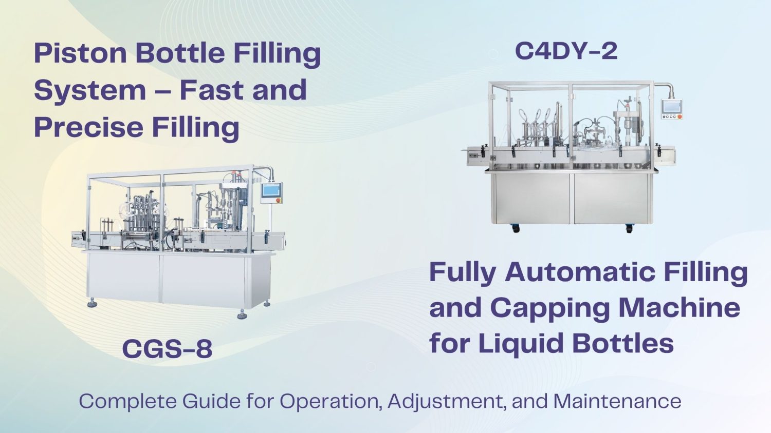
C4DY-2 is designed for different kinds of liquids with its two types of pumps, piston and peristaltic. CGS-8 is a fully automatic piston bottle filling machine with 8 filling heads to feed and press caps quickly and smoothly.
The operation and adjustment procedures of these two automatic liquid filling and capping machines are similar. But the following steps are provided for basic understanding and reference only. For detailed operation instructions, please refer to the user manual or contact our technical team.
Section 1: Operating Procedures
Step 1: Manually put the vials into the vial inlet of the vial feeding mechanism, and then push the vials forward to the vial feeding turntable.
Step 2: The vials on the turntable automatically enter the conveyor belt inlet in the anticlockwise rotation direction under the guidance of the vial-feeding guide plate and are orderly transported into the vial feeding turntable by the conveyor belt.
Step 3: When bottles enter the filling station, they will be set in a fixed position by two bottle-controlling cylinders, one of which is moving ahead of and the other moving behind bottles that are to be filled.
Step 4: Then the filling needle tube lowers and is inserted into the bottle for filling.
Step 5: After filling, these two cylinders move away, and the filled bottle on the belt goes into the main rotary table for the next phase.
Step 6: The cap is conveyed into the capping location at a certain speed. When the filled bottles are rotated to be under the cone-shaped unit, the capping cylinder works to lower the capping head, and the cap will be pressed by the movable hard plate through the cap location into the bottle opening.
Step 7: After capping, the capped bottle is pushed to the conveyor belt by the bottle pushing bar.
Section 2: Adjustment Procedures of Main Parts
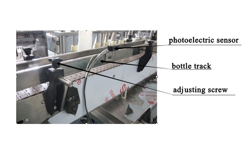
1. How to adjust the conveyor belt?
Step 1: Loosen the adjusting screw to adjust the spacing of the bottle blocking bar according to the size of the bottle diameter. Keep the spacing 1–2 mm longer than the bottle diameter so that the bottle can be conveyed smoothly. Then tighten the adjusting screw.
Step 2: Adjust the tightness of the conveyor belt to ensure that the bottles are conveyed without shaking, falling over, or being unable to move.
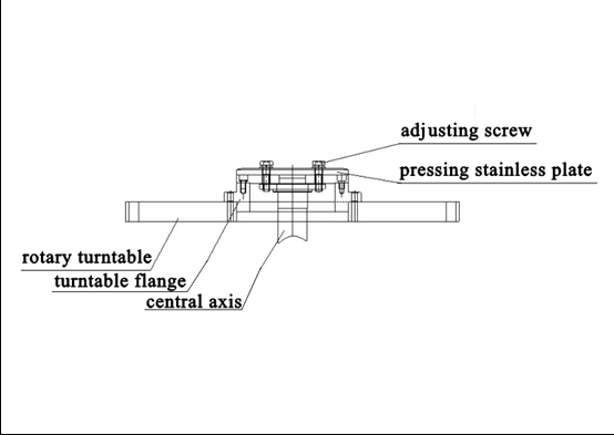
2. How to adjust the main rotary turntable?
Note: The bottle toggle mechanism has been set before leaving the factory, so please do not adjust it unless necessary.
Step 1: Loosen the adjusting screw, turn the upper and lower tray of the main rotary table.
Step 2: Adjust the position of the toggle slot to synchronize the filling head with the action of the toggle table, and then lock the adjusting screw.
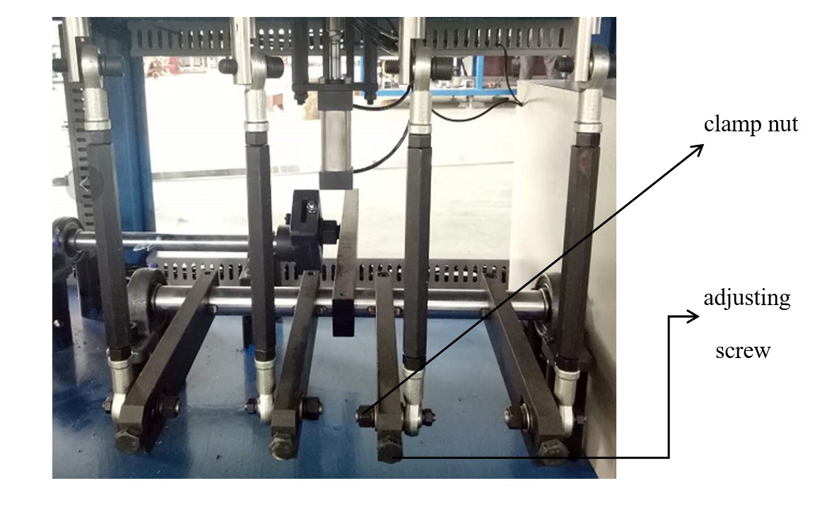
3. How to adjust the loading capacity of the metering pump?
Step 1: Loosen the clamp nut, and turn the adjusting screw and adjusting nut to change the overall loading capacity of the four metering pumps.
Step 2: After the adjustment is done, tighten the clamp nut and adjusting nut.

4. How to adjust the overall capacity of the metering pump?
Step 1: Loosen the clamp nut and turn the adjusting screw to change L (the shape of the two rods here). Run the mechanism to see whether the required amount of liquid can be filled in the bottles.
Step 2: When the adjustment is done, tighten the clamp nut.
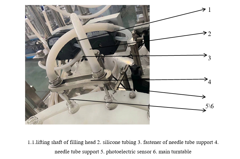
5. How to adjust the filling needle?
Step 1: Unscrew the clamp nut on the needle tube support.
Step 2: Adjust the distance between the needle tubes according to the diameter of the bottles. Then adjust the height of the filling needle tube according to the height of the bottle.
Step 3: Screw the nut.
Section 3: Maintenance Guides
Note 1: Add mechanical oil (N68) to the reciprocating parts of bearings and gear transmission parts, such as reciprocating shafts, lifting shafts, rotating parts, and running swing parts (where there are oil holes or oil cups) twice a day.
Note 2: Add grease to the cam grooves once every half month and once a month at the oil nozzle.
Note 3: The cam protractor and speed reducer need to be replaced once a year.
Note 4: When cleaning the molds, parts, and the surface of the equipment, do not scrape or strike with metal tools so as not to damage the parts. Do not rinse with water.


