NOTICE
- The following procedures are intended for the Anxine IBC Blender only. For other brands, refer to the original manufacturer’s instructions.
- Always disconnect the power supply before performing maintenance, cleaning, or mold changeover.
- Only trained and authorized persons are permitted to work on the equipment.
- Your equipment may vary from images or videos due to ongoing upgrades.
- If any part of this guide is unclear, contact Anxine for technical support before proceeding.
Section 1: Installation Guides
Installation Requirements
- To ensure stable operation of the equipment, the installation site must have a concrete foundation with sufficient depth, level and even ground, and a load-bearing capacity not less than 1000 kg/m², which meets or exceeds the installation requirements.
- The workshop where the machine is installed must be equipped with a power supply consistent with the equipment requirements. In addition, a PE grounding interface must be provided, and the supply voltage must comply with the voltage specified in the contract.
- The mixer has been fully debugged and tested before leaving the factory. For transportation convenience, it is disassembled into three parts. Therefore, proper installation at the site is required to ensure the accuracy of the hopper’s home position. It is generally recommended that installation be carried out under the guidance of professional personnel.
Installation Procedures
Step 1: When installing the main unit, determine the installation position, safely hoist the main unit, align it with the base mounting holes, and lower it slowly and vertically.
Step 2: After fixing the base, install and tighten all fixing bolts. Then, install the top support column (the top column should be welded securely to the building structure by the user during installation to ensure vertical stability of the equipment).
Step 3: When installing the connecting arm, align the arm with the corresponding connection holes, insert it, install the pressure plate, and tighten the pressure plate bolts.
Step 4: Before connecting the power, ensure that the power supply matches the equipment requirements. Then wait for the trial run.
Step 5: Before the trial run, read the User Manual carefully to familiarize the mechanical structure and check if the electrical system is in good condition.
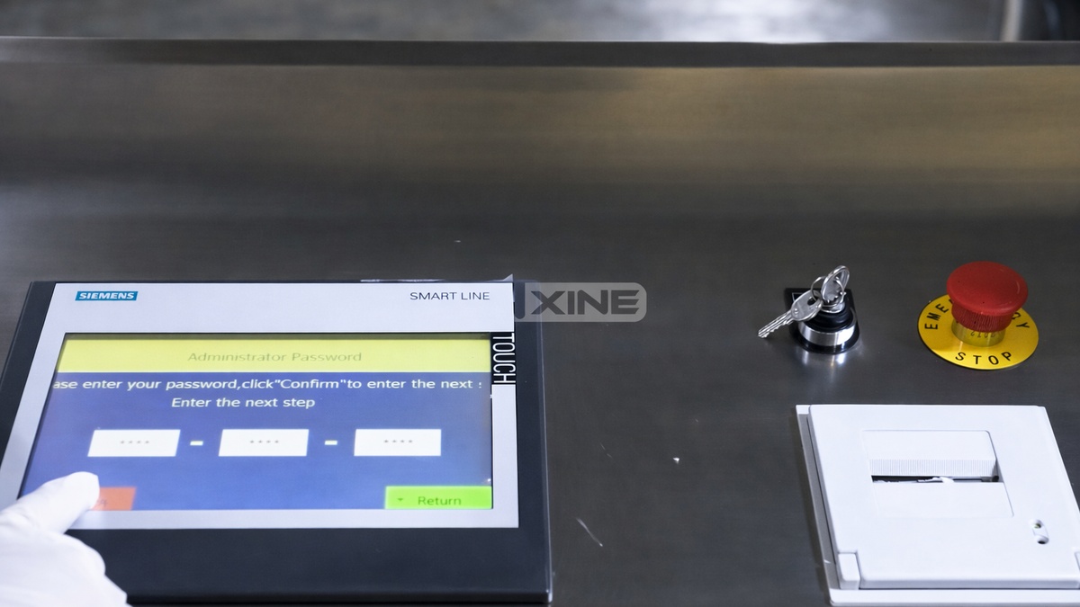
Step 6: Once confirmed, switch on the power and turn the lockable switch on the control cabinet. When the system home page appears on the screen, manually enter the operation interface.
Section 2: Operation Procedures
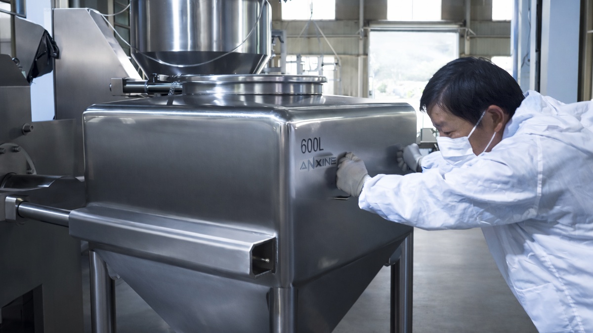
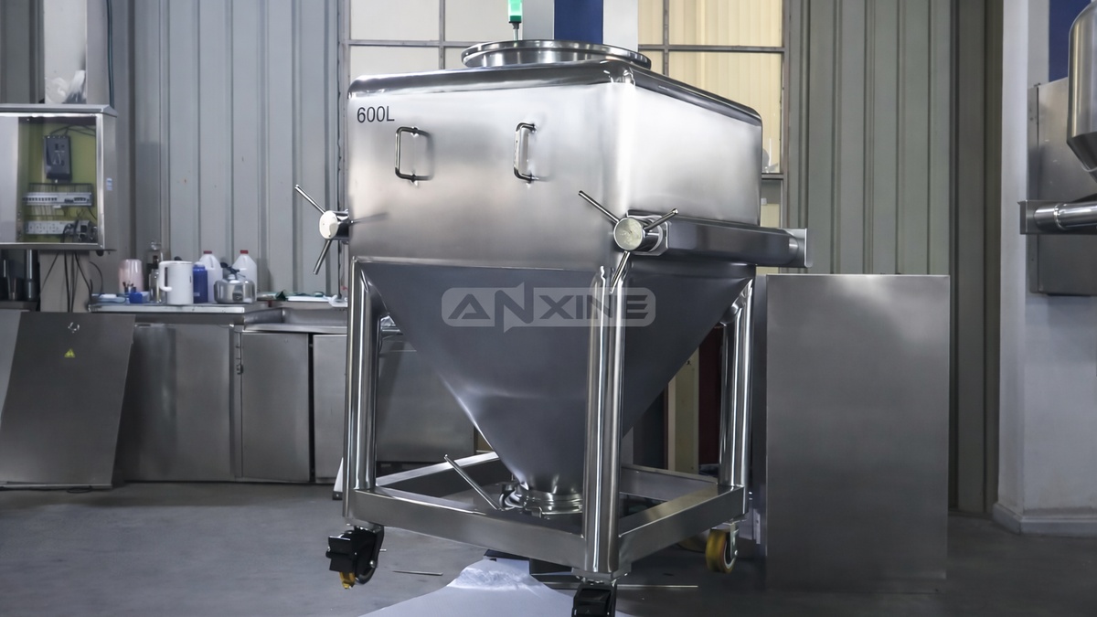
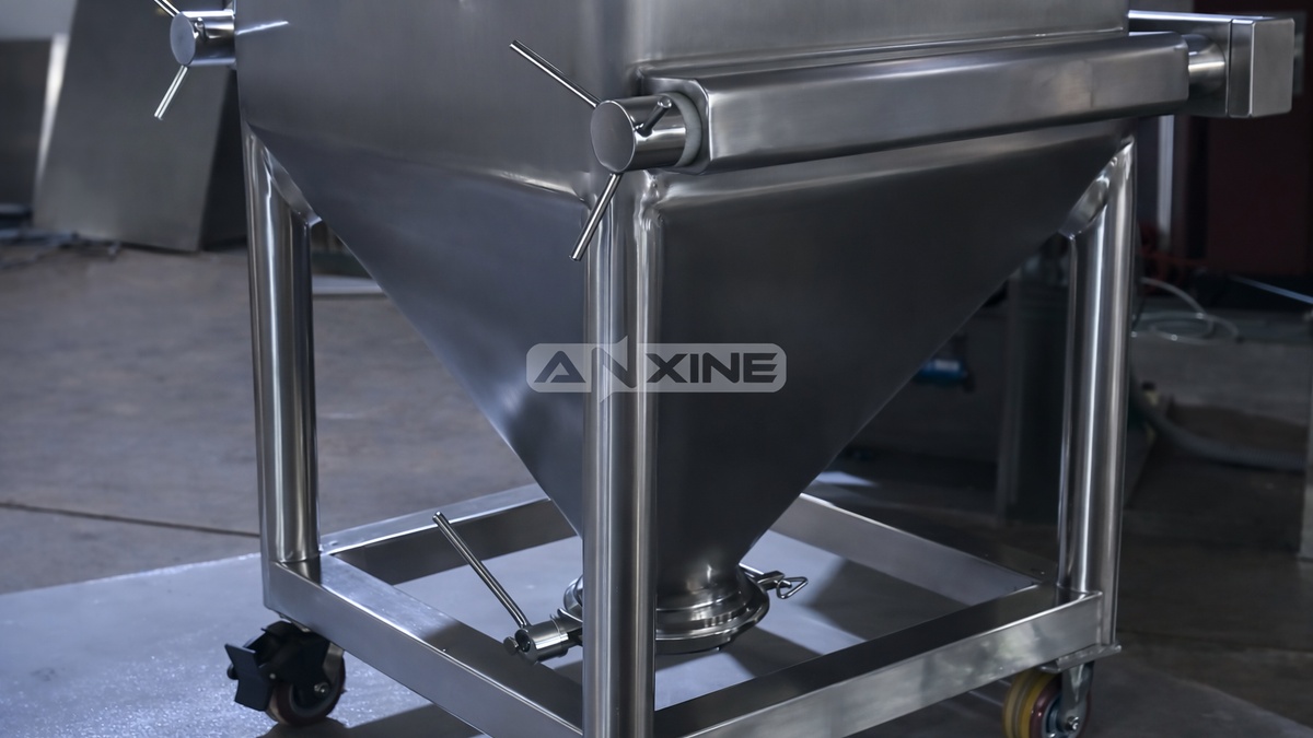
Step 1: Push the mobile IBC bin toward the lifting column. Align the bin so the lifting forks slide directly into the hollow side brackets.
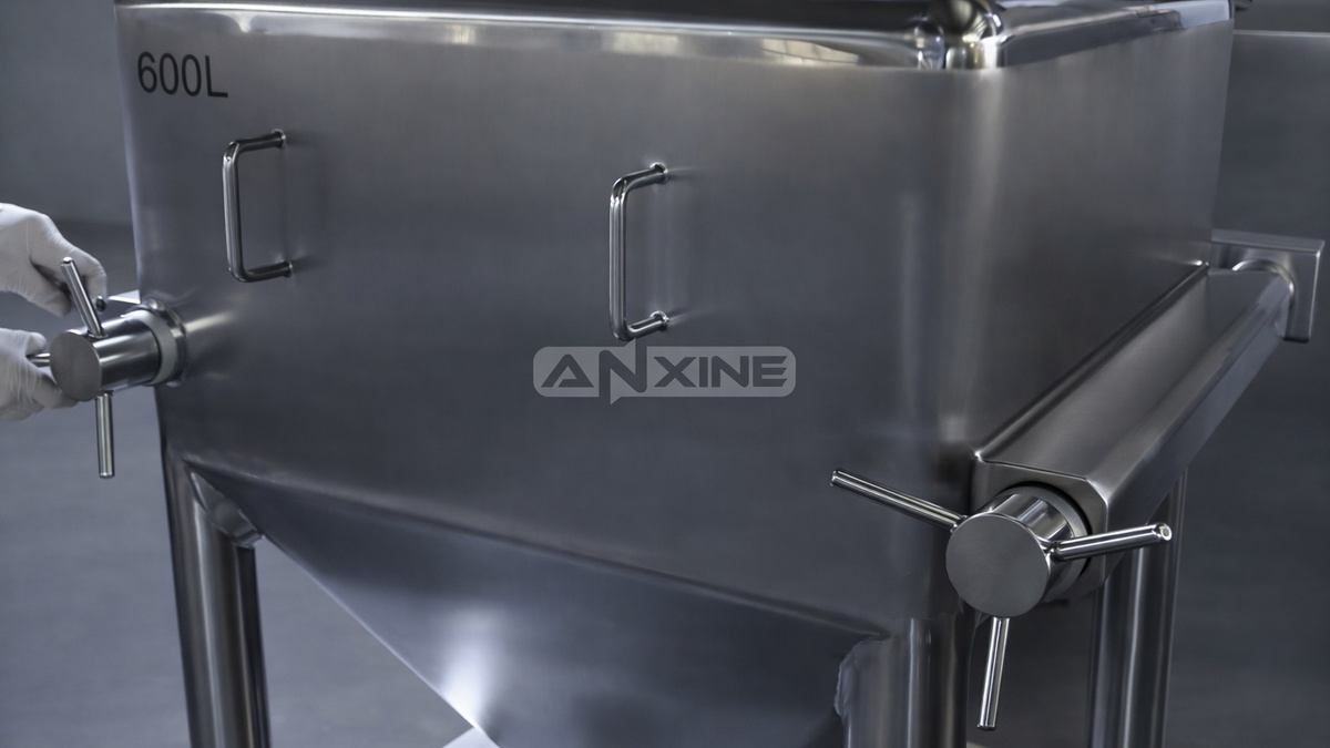
Step 2: When the IBC bin is in position, insert a nylon bushing into the exposed end of each lifting fork. Then engage a manual locking handle over the bushing.
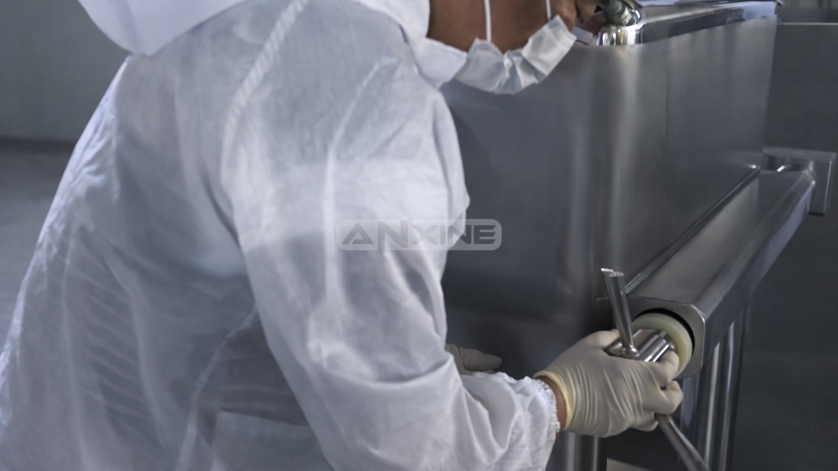
Step 3: Rotate the handle clockwise to lock the bin onto the hoist. Perform this on both the left and right sides to ensure the load is balanced.
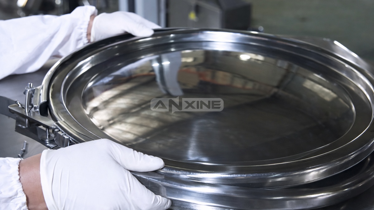
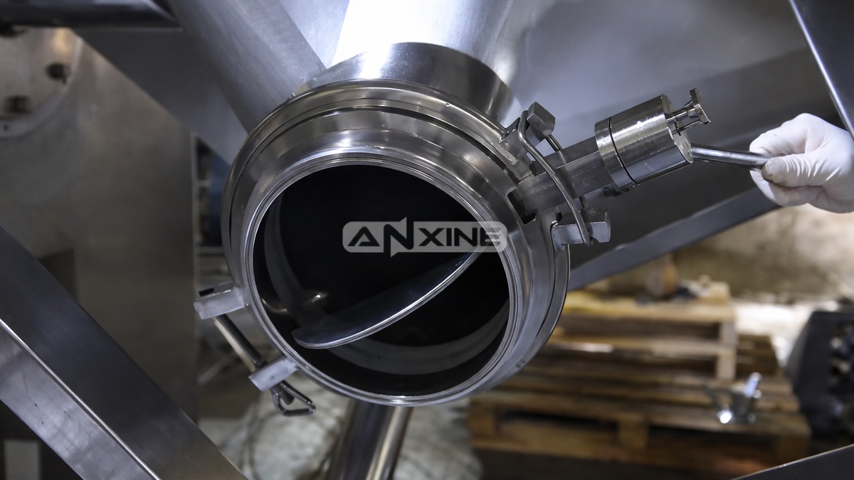
Step 4: Unlatch the locking clamp at the feed inlet of the IBC bin. Then remove the cover and load the powder ingredients into the bin. Once finished, replace the cover and re-engage the clamp to seal the inlet.
Step 5: Go to the HMI touchscreen panel. Select your language and user access level. Enter the password to unlock the system. Choose the desired operation mode: Manual or Auto. In Manual mode, press the Lift button. The post hoist will raise the bin vertically.
Step 6: Monitor the bin as it rises to the operational height. Confirm the swing zone is clear of all personnel and obstacles.
Step 7: Once the bin is at the correct height, start the blending cycle. The IBC bin will rotate end-over-end. This tumbling action creates diffusion mixing for a uniform blend.
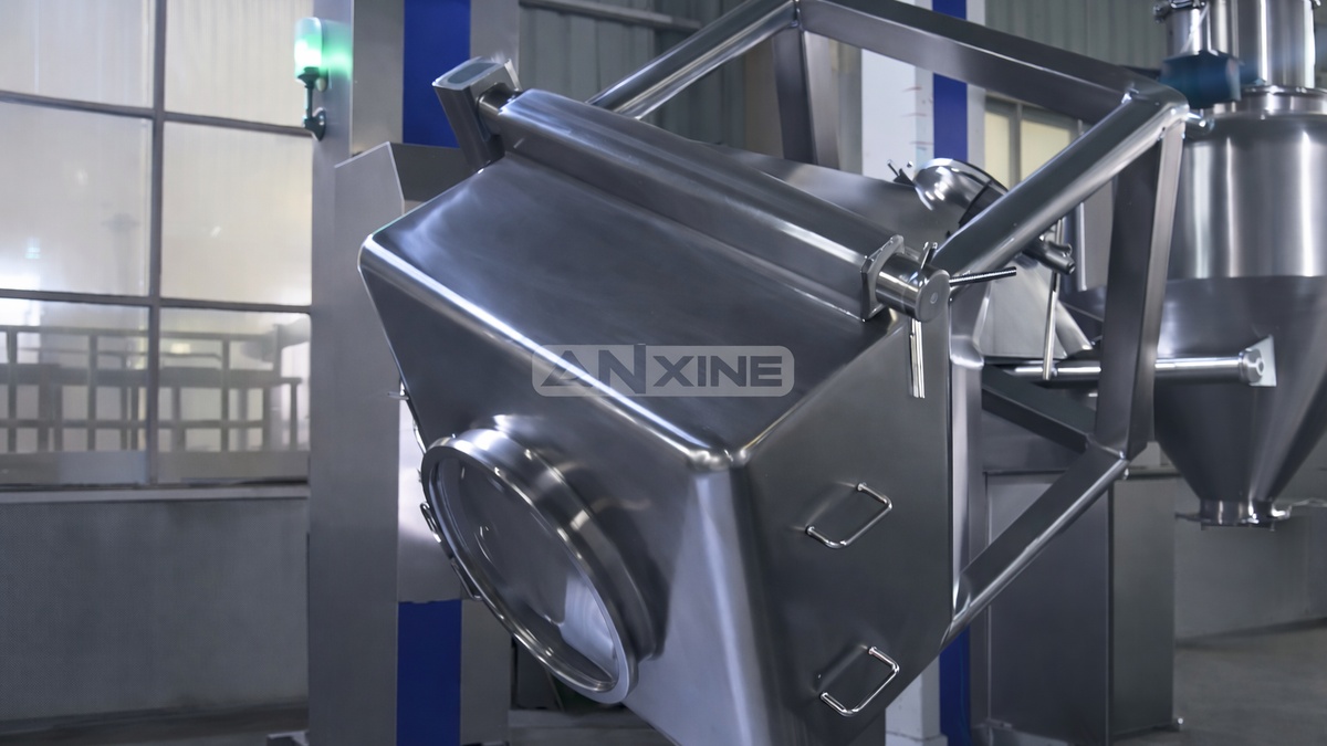
Step 8: After the set time elapses, the blender stops with the bin in a vertical, upright position. Pull the handle at the discharge outlet to open the butterfly valve. The mixed powder will flow into the collection bin below.
Step 9: When the bin is fully emptied, press the function button to lower it back to floor level. One blending cycle ends.
Want to see these steps in action? Watch the full operation video below. The video demonstrates the entire post hoist IBC blending process from bin positioning to discharge.
Section 3: Maintenance Guides
- Enough lubrication grease was added during assembly. No need to add grease during daily operations. During intermediate or major maintenance, the lubrication grease should be replaced with NLGI Grade 2 calcium-based grease.
- The hydraulic system requires approximately 20 liters of ISO VG 46 anti-wear hydraulic oil (use ISO VG 32 in cold climates). Please note that the oil must be filled through an 80-mesh filter to prevent foreign materials, such as fiber, sand, and iron powder, from entering the fluid.
- The main shaft bearing is located at the front end of the rotating/blending reducer and should be lubricated once a month with 150 grams of NLGI Grade 3 lithium-based grease. Before filling, remove the double-half cover and bearing cover, then fill the grease into the bearing gaps with a grease gun.


