NOTICE
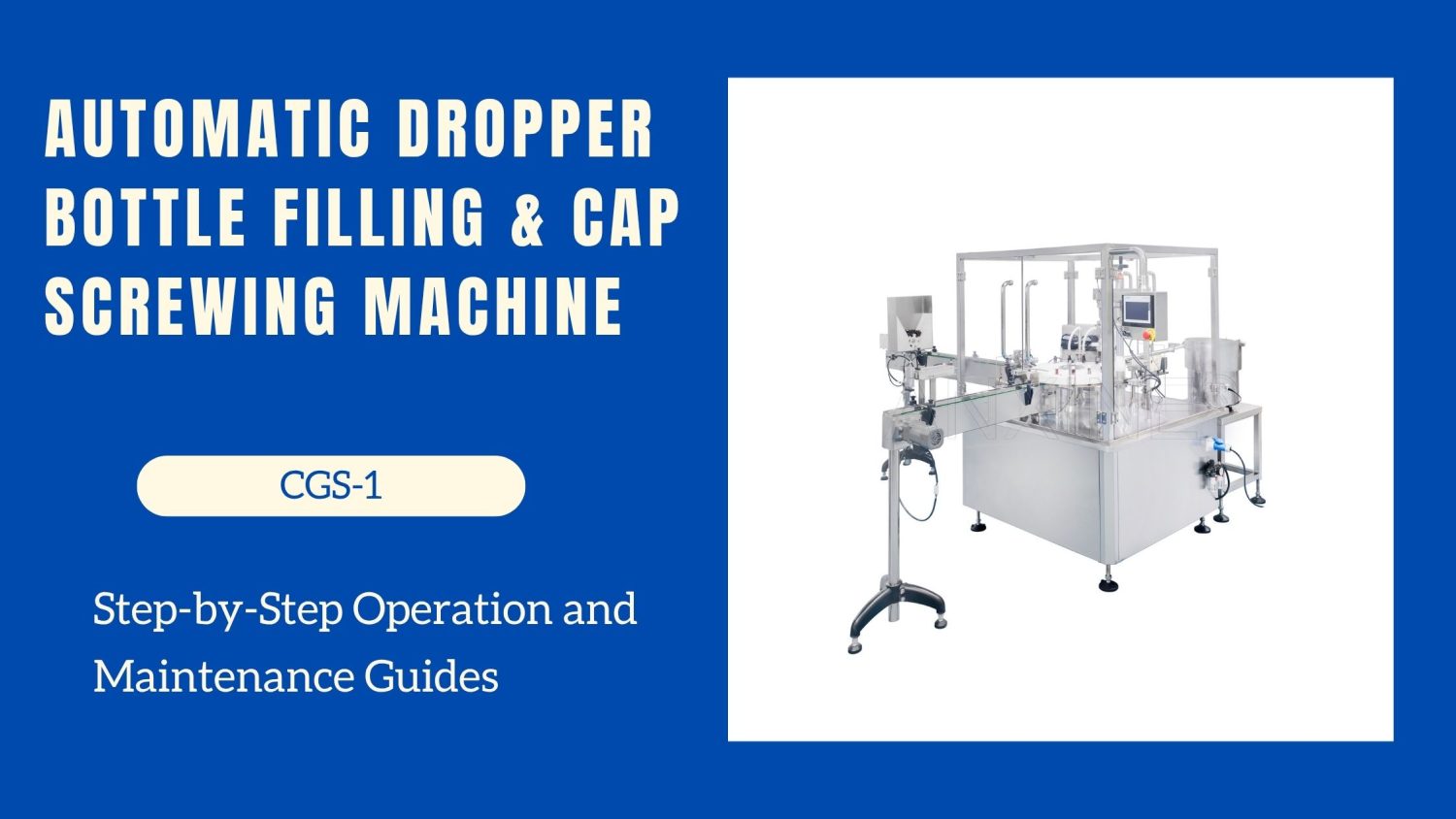
- The following procedures are intended for the Anxine CGS-1 only. For other brands, refer to the original manufacturer’s instructions.
- Always disconnect and lock out both the power and compressed-air supplies, and release all residual pressure, before performing maintenance, cleaning, or mold changeover.
- Only trained and authorized persons are permitted to work on the equipment.
- Your equipment may vary from images or videos due to ongoing upgrades.
- If any part of this guide is unclear, contact Anxine for technical support before proceeding.
Section 1: Operation Procedures
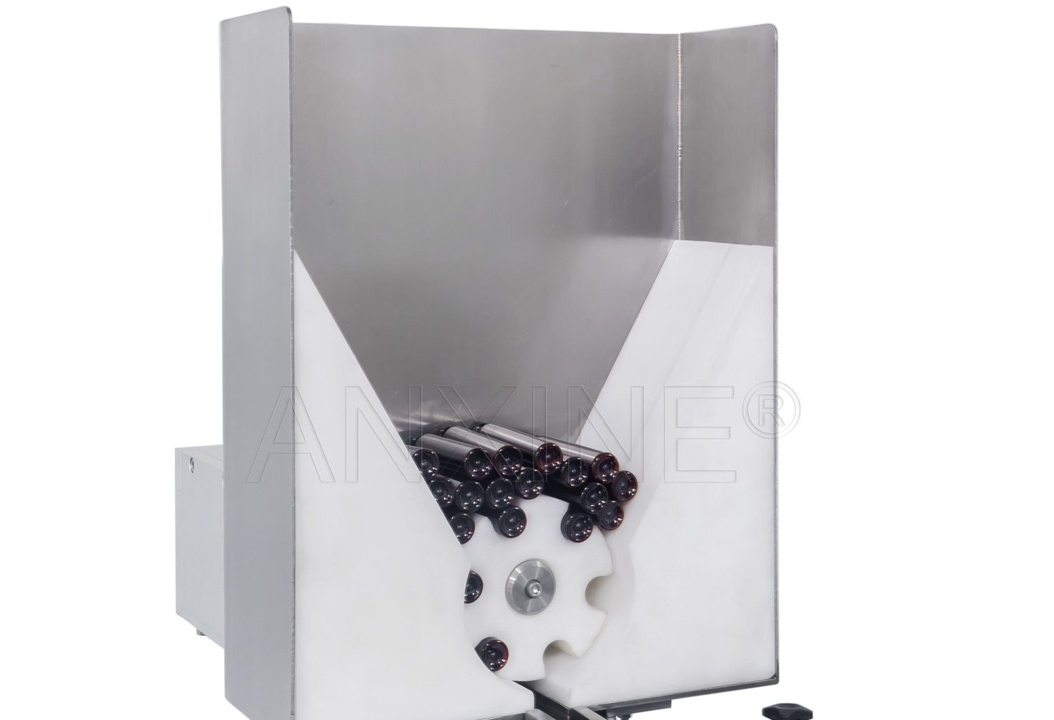
Step 1: Put bottles in the hopper, and the bottles can be carried to the conveyor belt with the rolls rotating.
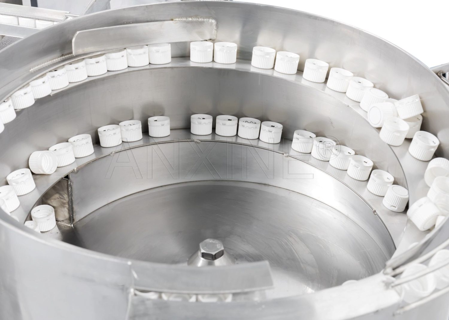
Step 2: Put caps into the vibrating disc and turn on the vibrator to adjust the speed so the caps enter the cap-sending track orderly.
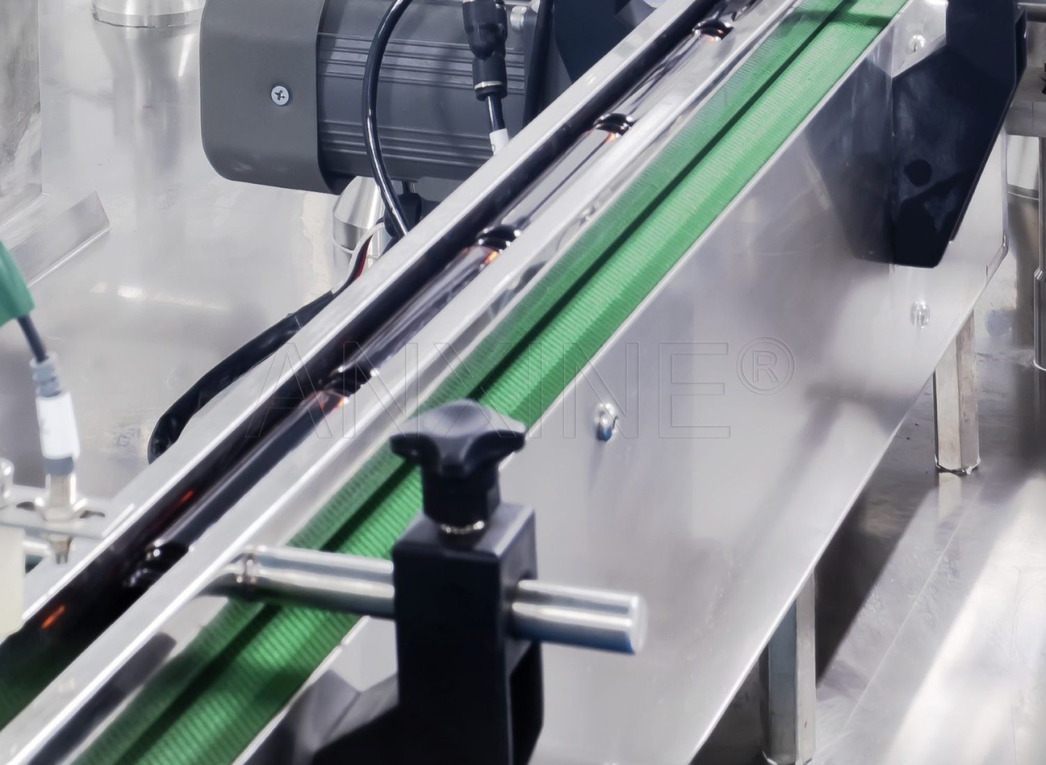
Step 3: Bottles are then transferred to the turning mechanism. When all bottles enter the track of the turning mechanism, the previously horizontal bottle is erected and inserted into the hole of the main turntable to be fixed.
Step 4: The bottles are transferred to the filling needle station. The filling needle descends into the bottle for filling. If there are no bottles or no bottles in position, the pump will stop via a photoelectric sensor.
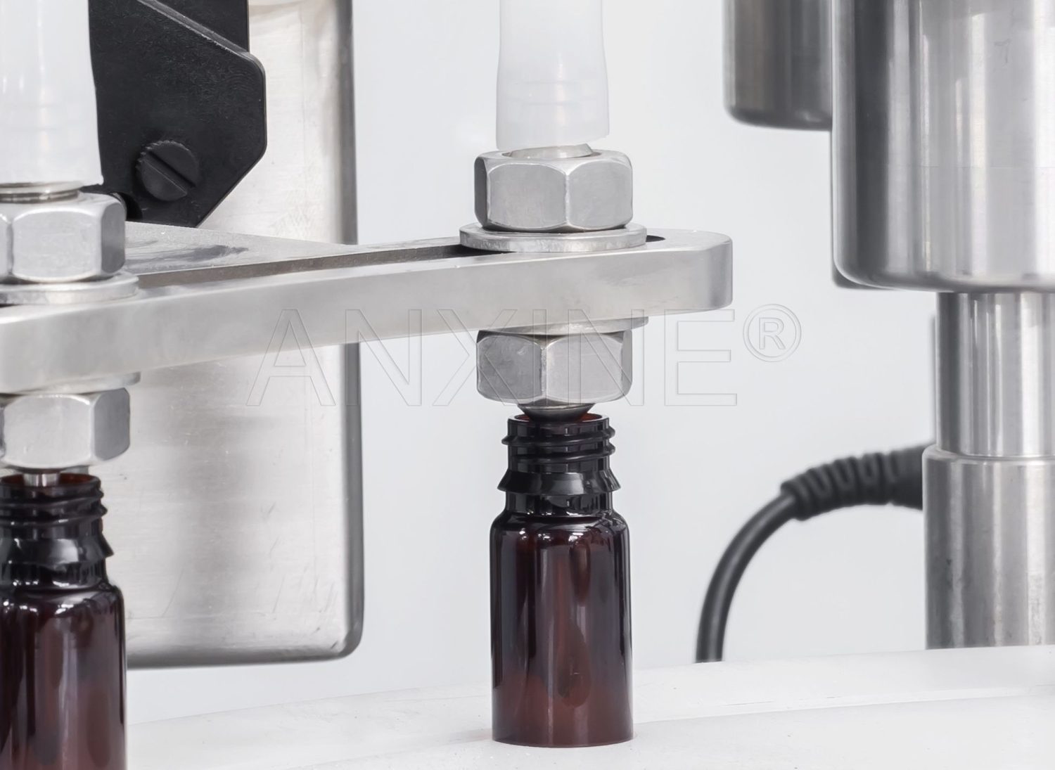
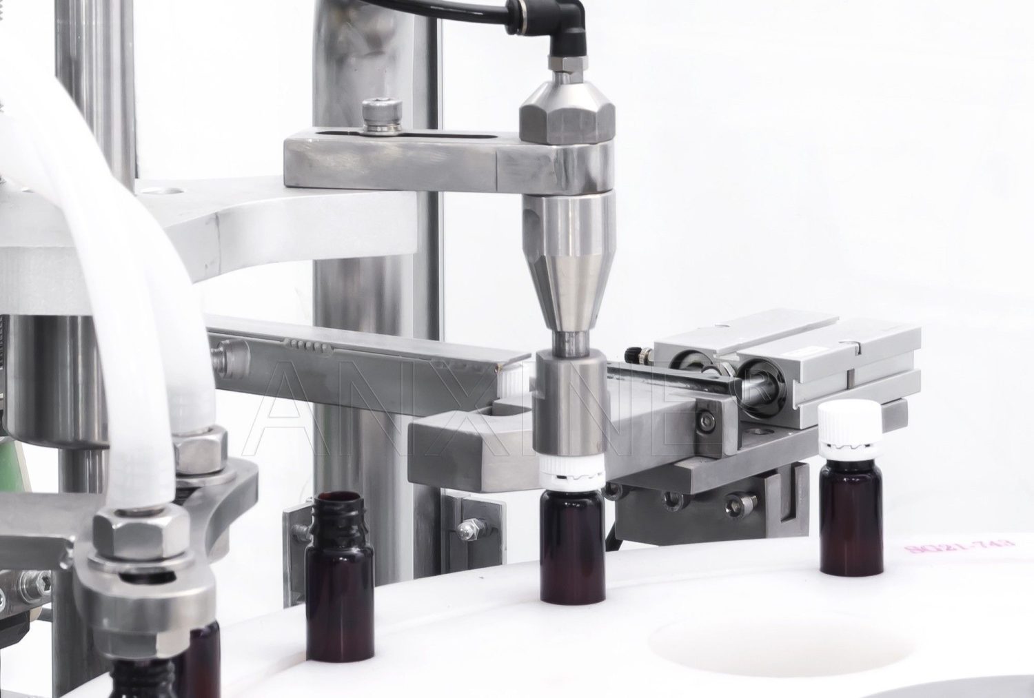
Step 5: The suction device moves down with the lifting shaft to pick up the cap, then moves up above the bottle and presses the cap onto the bottle. When there is no bottle, the cap will not be pressed, controlled by a photoelectric sensor.
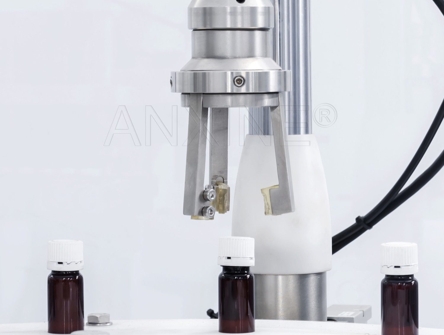
Step 6: When bottles enter the capping position, the capping motor drives the capping hands to rotate and tighten the cap.
Section 2: Adjustment Guides
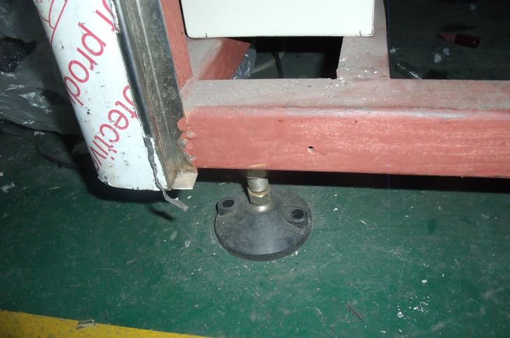
1. Adjustment of the machine feet
By adjusting the height of the four machine feet, the equipment can also be in a horizontal state, and the connection ports of the two pieces of equipment are matched so as to ensure the smooth operation of the whole line.
2. Adjustment of the vibrating frequency
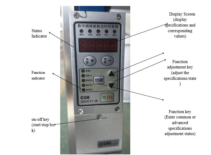
Open the electrical box. The speed of bottle-arranging can be adjusted by pressing the button on the control box.
3. Adjustment of the capping mechanism
Note: Attention needs to be paid to the maintenance of the assembly, the entire running components will fail to work.
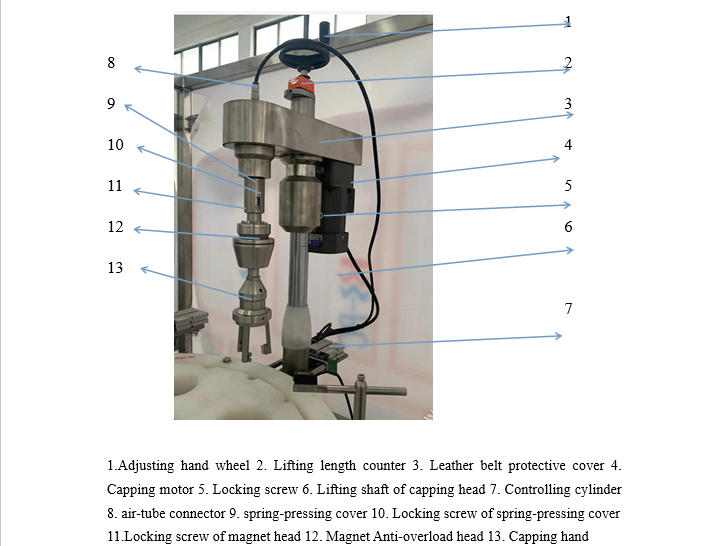
Step 1: The compression spring has already been adjusted before. If it is necessary to adjust the capping force, loosen the locking screw of the magnet overload protector and rotate the protector to change the spacing between the internal magnet rings.
Step 2: Rotating the protector upwards means increasing it and vice versa. After the force adjustment, tighten the locking screw. The protection would ring idle when the force is over the limit to prevent wearing the cap.
Step 3: The lifting shaft is used to adjust the overall height of the capping mechanism. Loosen the locking hand wheel of the shaft before adjusting.
Step 4: The lifting length counter shows the position of the capping head, and the center positioning of the filling head should be aligned with the hole position of the main turntable.
Step 5: The up and down movement of the cap head is driven by the roller at the end of the lifting shaft, which is driven by the cam underneath the frame.
Step 6: The roller and the cam slot stone need to be kept parallel.
Step 7: There should be a slight gap of 2 mm between one side of the lifting shaft and the transverse section of the cam.
Section 3: Maintenance Guides
Note 1: Bearings, gear transmission parts, rotating and running swing parts, reciprocating shafts, and lifting shafts need to be filled with N68 mechanical oil twice a day.
Note 2: Cams need to be greased once every half a month, and the engine oil in cam indexers and gearboxes needs to be changed every year.


